Audio Guide Charging Cabinet Specification
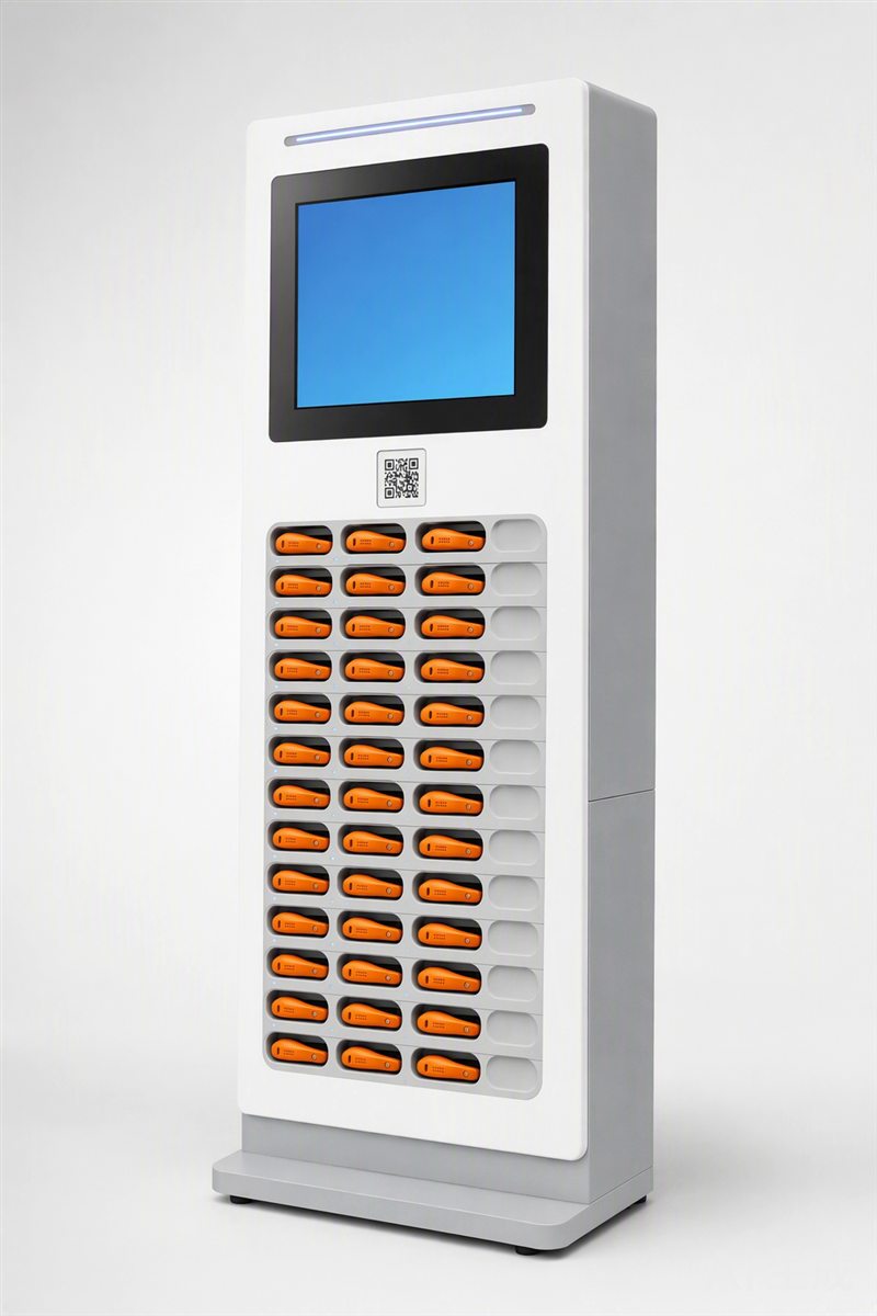
The audio guide charging cabinet is a throughput gate, not a storage box. Its specification determines whether a museum’s fleet clears 400 devices through overnight charging before opening, or stalls at 280 because 12 bays have degraded past stable connection. Bay count matters only alongside insert service life, pogo pin geometry, and thermal management during sequential charging. WingPhoenix builds to this reality: every rental cabinet ships with field-replaceable inserts, each certified to 500 full insertion cycles under load, and every hardware revision carries its own CE RED and battery documentation — not a blanket certificate. This is how fleets survive peak day.
Bay Count Is Not Throughput
A cabinet rated for 60 bays delivers 60 devices only if all 60 make stable contact for the full charge cycle. In practice, bays degrade unevenly: those near ventilation intakes retain lower thermal stress, while bottom-row bays see higher cumulative current draw from stacked charging loads. Throughput is the number of bays that maintain ≤120 mΩ contact resistance after 400 cycles — not the number printed on the label. That figure is validated per insert batch, not per cabinet shipment, and appears in the FQC report shipped with each order. For context, the guide player and open-ear receiver both draw peak 1.8 A during fast-charge phases, amplifying resistive heating at weak contact points.
Pogo Contacts Are Consumables, Not Components
Pogo pins are specified by stroke length, spring force, plating thickness and base alloy — not just pitch or diameter. WingPhoenix uses 0.3 µm gold-over-nickel plating on beryllium copper stems, tested to 500 cycles at 1.5 N actuation force. Below 0.2 µm, resistance drift exceeds 15 % and intermittent disconnects begin. No firmware update corrects this. Replacement inserts are stocked and quoted separately; they are not included in MOQ calculations. The pocket translator, for example, uses the same insert footprint as the G1 player — enabling cross-device cabinet reuse where charging profiles align.
The Closing-Time Queue Is a Mechanical Test
“Closing-time queue” refers to the final 90 minutes before venue opening, when all devices must be verified as charged and ready. It is not a software timer — it is the thermal window within which the cabinet’s PCB, connectors and cooling path sustain full-load operation without voltage sag or thermal throttling. Cabinets undergo 72-hour continuous load testing at 95 % ambient humidity and 35 °C ambient — conditions matched to European summer museum basements. This test is part of the how we build and test protocol, not an optional add-on.
Replaceable Inserts Enable Long-Term Fleet Control
Each insert houses the pogo pins, alignment guides and strain relief for the device’s charging port. It is mechanically isolated from the cabinet’s power bus and control logic. When wear exceeds threshold, only the insert is swapped — no rework of mainboard or firmware required. This design supports OEM/ODM services: custom port layouts, alternate pin counts or multi-voltage support are implemented at the insert level, not the cabinet level. Insert revisions are tracked separately in the QC gate log and documented in the CE RED document checklist.
What This Cabinet Cannot Do
This cabinet does not manage device-level firmware updates, schedule staggered charging based on battery state-of-charge, or detect internal cell imbalance in aged devices. It provides regulated 5 V / 2.4 A per bay, with over-current and over-temperature cut-off — nothing more. No report exists for “smart charging efficiency” or “AI-optimised power sequencing”, because those functions reside in the device, not the cabinet. Importers should reject any supplier claim linking cabinet firmware to battery longevity or adaptive load balancing. Those claims imply undocumented software layers that conflict with CE RED’s intentional radiator scope and invalidate the MOQ, sampling and lead times policy.
| Decision Point | Factory Policy | Procurement Check |
|---|---|---|
| Bay count guarantee | Validated at 400 cycles, ≤120 mΩ per bay | Request FQC report excerpt for latest insert batch |
| Pogo pin replacement | Insert-level only; cabinet frame not serviced | Confirm insert MOQ and lead time separate from cabinet |
| Compliance scope | CE RED, FCC, RoHS 3, UN38.3 booked per hardware revision | Verify lab name and test date match shipping documentation |
| Thermal validation | 72 h at 35 °C / 95 % RH, full load | Ask for thermal imaging log from last IQC gate |
| Firmware role | Only status LED control and basic fault flagging | Reject any “adaptive charging” or “battery health analytics” claim |
| Cross-device support | G1, G2 and A1 share insert footprint where charging profile matches | Validate voltage/current envelope compatibility per device model |
- Confirm insert service life (500 cycles) applies to your device’s port geometry and mating force
- Require FQC report showing contact resistance at 100, 250 and 400 cycles
- Verify thermal test conditions match your venue’s basement or storage environment
- Check that CE RED documentation lists your exact hardware revision, not a generic version
- Ensure UN38.3 and SDS are shipped with first container, not emailed later
Peak-day resilience starts with insert-level specification, not cabinet aesthetics. To proceed, request the insert compatibility matrix for your AI Audio Guides line, confirm your venue’s ambient conditions against our thermal test parameters, and ask for the latest FQC report excerpt for the G3 cabinet revision you intend to quote. All documentation will be issued per hardware revision — no exceptions.
Questions buyers ask
Why does one cabinet model survive peak season while another fails daily?
Because throughput depends not on nominal bay count alone, but on how many bays remain functional after 18 months of 300-cycle-per-day use, and whether worn contacts can be replaced without scrapping the entire unit.
What compliance documentation must ship with each cabinet revision?
CE RED (EN 300 328, EN 301 489, EN 62368-1), FCC Part 15 B/C, RoHS 3, REACH SVHC screening, and battery UN38.3 + SDS — all booked per hardware revision with an accredited laboratory.
A sample failed at 270 cycles — what should we check before ordering?
Whether the test used the same pogo pin spec and insert material as your final build; contact wear is tied to the replaceable insert design, not the cabinet frame.
What claim about charging speed or smart scheduling do suppliers routinely overstate?
That firmware can compensate for mechanical wear in pogo contacts — it cannot. Contact resistance rise is physical, not algorithmic, and no software update restores conductivity once the gold plating is abraded below 0.2 µm.
Related: more on ai audio guides · buyer guides · customisation tiers